3D printed 10" homelab rack with ESP32 fan control for Strix Halo cooling
Problem
Over time my office accumulated lots of devices just standing around, a NAS, a network switch, a "home server" and some rpis sitting around connected with a mess of cables. I came across the "labrax" project to put all of this into one neat case.
The heat coming from the EVO-X2 used for local inference was also a big problem, it's an AMD Ryzen AI Max+ 395 "Strix Halo" with 128GB of unified LPDDR5X, running llama-swap in front of llama.cpp so I can hot-swap models. Under sustained inference it sat at 98C, probably getting throttled.
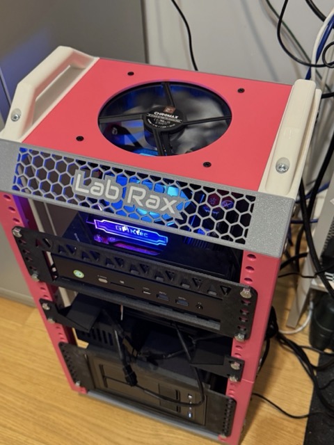
The rack: Lab Rax
I printed the Lab Rax, a modular 10" rack system by Michael Klements. There is an original version using brass heat-set inserts and a bolted version needing only M6 button heads and nuts. I went with the bolted version, so it comes apart cleanly when I re-shelf something. The full collection has shelves, blanking plates and fan holders, and The DIY Life has a good write-up.
Check your filament before you start. PLA is all I had initially, but PLA creeps and softens well below the temperatures this rack was expected to experience. That gave me a good reason to upgrade my 3D printer nozzle to hardened steel so that I can print PETG.
Printed on a Bambu P1S. (256mm bed limit)
Custom parts, designed by an LLM
The frame is downloaded, but my components are not standard rack gear. Three custom parts:
- Top fan panel. The bundled Lab Rax panel is drilled for a 120mm fan; I wanted a 140mm Noctua. Same 228 x 171.5 x 3mm footprint, one round 133mm cutout (140mm frame leaves a ~3.5mm seating lip), four 4.4mm holes on the standard 124.5mm square.
- 1U fan mount. Open-frame bracket holding a 140mm fan flat, so it moves air vertically through the rack. Ears bolt to the front rails, wings carry the fan centred in the case depth (110mm into 220mm).
- Enclosure for the electronics - vented screw-down box with M3 corner bosses.
I was impressed by how easy it was to get an LLM to generate CAD parts.
What made it work:
- Give it real measurements. use a caliper, take photos, draw simple diagrams, this all helped.
- Use the correct vocabulary. Collar, boss, gusset, fillet, pilot hole, seating lip.
- Always open the result and measure it before printing. Open your obj and use the measuring tool to check critical dimensions (it does make mistakes).
I had to make some hand edits afterwards, but it got me to the end result much faster.
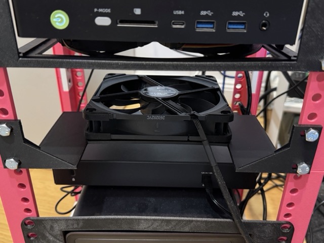
Stripping the EVO-X2
The EVO-X2 came out of its case entirely. Inside a closed rack it does not need a second shell, and that shell was what trapped the heat.
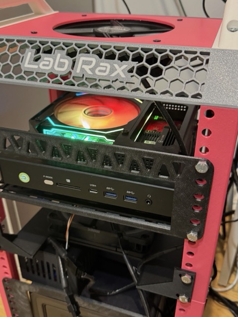
The fans
Two Noctua NF-A14x25 G2 PWM chromax.black 140mm fans - one in the top panel, one on the shelf below the EVO-X2.
These are superb. PWM controllable from 1500rpm all the way down, and at low speed they are completely silent.
The problem, I had no way to control the 4-pin fans. Another mini-project.
The controller
I used an ESP32 to read the rack air temperature from a DS18B20 (mounted right behind the EVO-X2, and that drives the fan PWM control.
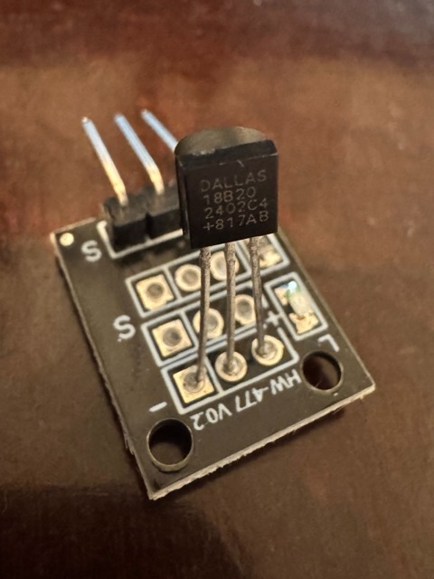
Design decisions
- Continuous proportional curve, not on/off.
- No power switching. The 12V line stays permanently on and only the PWM signal is modulated, at 0% duty the fans stop.
- One 12V brick. Feeds the fans directly and a buck steps it to 5V for the ESP32.
duty
100% |                          _________
     |                 ________/
     |         _______/
 ~0% |________/
     +-------|--------|--------|--------
            30C      40C      50C
Firmware
The core function simply converts temperature to "fan duty" (8-bit output).
// fan_curve.h - pure temperature -> PWM-duty mapping.
static const float FAN_TEMP_MIN_C = 30.0f;  // at/below this: fans idle (0% PWM)
static const float FAN_TEMP_MAX_C = 50.0f;  // at/above this: 100% PWM

// Map a temperature (deg C) to an 8-bit PWM duty (0..255).
// Invalid readings -> 255 (fail-safe full speed).
static inline uint8_t tempToDuty(float tempC) {
  if (isnan(tempC) || tempC < -40.0f || tempC > 125.0f) {
    return 255;  // fail-safe: sensor fault / disconnected (DS18B20 = -127)
  }
  if (tempC <= FAN_TEMP_MIN_C) return 0;
  if (tempC >= FAN_TEMP_MAX_C) return 255;
  float frac = (tempC - FAN_TEMP_MIN_C) / (FAN_TEMP_MAX_C - FAN_TEMP_MIN_C);
  long duty = lround(frac * 255.0f);
  if (duty < 0) duty = 0;
  if (duty > 255) duty = 255;
  return (uint8_t)duty;
}
Any invalid reading returns 255. setup() also writes 255 before the first read. So if anything goes wrong, fans go to 100%.
Testing
Simulation. Wokwi has an ESP32 and a DS18B20 slider but no 4-pin fan. It was fine for simple simulations, but getting a slot to compile on the free tier was flaky.
Benchtop. On a current-limited benchtop PSU at ~0.8A.
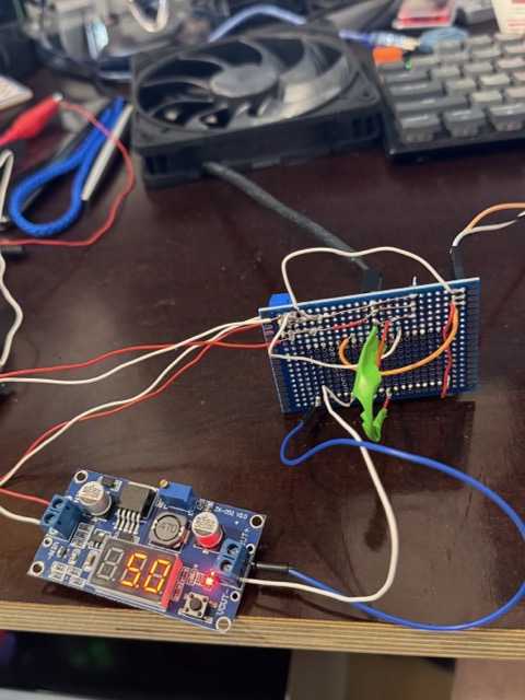
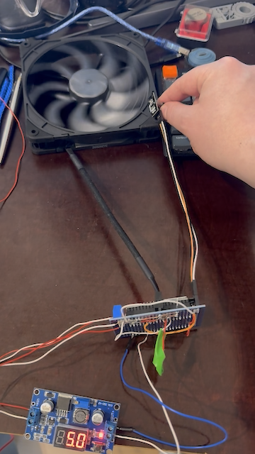
Holding the sensor between my fingers was enough to activate the >30C fan level.
The permanent build
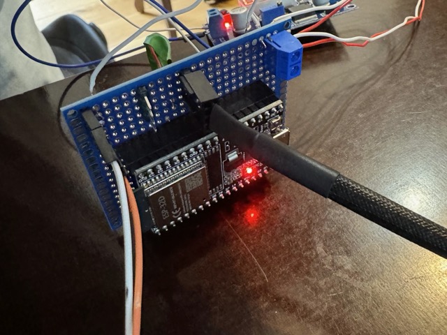
This was my first real soldering project.
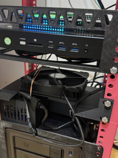
The DS18B20 sits at the exhaust side of the EVO-X2, so it should engage whenever inference is happening.
Results
The Lab Rax works great to tidy up my office, and it looks interesting. But I'll probably go for a bigger rack next time.
The EVO-X2 temprature is now down to around 88C under sustained inference.
The Noctua fans are unbelievably silent, I'm really impressed. Below 30C the fans are stopped, and even once they are running at low duty I cannot hear them. They only ramp up while a model is generating.
Parts
| Part | Role |
|---|---|
| ESP32-WROOM-32D | LEDC 25kHz PWM + 1-Wire |
| DS18B20 (KY-001 module) | Rack air temperature, onboard 4.7k pull-up |
| 2x Noctua NF-A14x25 G2 PWM chromax.black | 140mm, ~0.14A @ 12V each |
| LM2596 buck converter | 12V to 5V for the ESP32 |
| 12V/2A barrel PSU, 5.5x2.1mm centre-positive | Single supply for fans + buck |
| 5.5x2.1mm female barrel jack to screw terminal | 12V entry point, no soldering |
| 5x7cm double-sided protoboard | The permanent build |
| M6 button head screws + nuts | Lab Rax bolted version |
| PETG filament + hardened steel nozzle | Rack, mounts, enclosure |
Keywords
#Homelab #10InchRack #LabRax #3DPrinting #PETG #ESP32 #DS18B20 #Noctua #PWM #StrixHalo #GMKtec #LocalLLM #llamacpp #CadQuery #Fusion360 #BambuLab